
A beginner’s guide
PlantText provides a *ton* of sample UML diagrams to get you going right out of the gate. Such a dizzying array, in fact, that you might get lost trying to sort out which one applies best to your situation. So we’re starting a new series on UML Diagrams to talk through the different types of UML diagrams, what they are, and when to use them.
We’re starting this series with use case diagrams because they are some of the most commonly used in UML. In the world of software engineering, they tend to be heavily leaned on early in a project to ensure that everyone on the team — from developers to stakeholders — has a clear understanding of how a system will behave, or be used.
But what exactly is a use case diagram? When should you use one? And how do you create an effective diagram? Let’s break it down.
What is a use case diagram?
A use case diagram is a type of Unified Modeling Language (UML) diagram that visually represents how different actors (users or systems) interact with a system to achieve specific goals (use cases). It’s a simplified, high-level view of what the system does and who interacts with it, focusing on functionality rather than internal processes or system architecture.
In a typical use case diagram, you’ll see:
- Actors: These are the users or external systems that interact with the system in question. An actor could be a person, another system, or even hardware that interacts with the software. For example, in a shopping app, actors might include customers, administrators, and payment gateways.
- Use Cases: These represent the goals or actions that actors perform with the system. They are usually described as verbs or actions, such as “Login,” “Place Order,” or “Generate Report.”
- System Boundary: This is the box that defines the scope of the system being modeled, encapsulating all the use cases within the boundaries of the system.
- Associations: These are the lines that connect actors to use cases, representing the interactions between them.
In short, use case diagrams define who does what with a system.
When should you use a use case diagram?
Use case diagrams are particularly useful in the early stages of software development when gathering and analyzing system requirements. Here’s how they shine:
- Defining scope: When kicking off a new project, use case diagrams can define the scope of the system and set clear expectations for what it will and won’t do. They give a high level view of the system’s functional requirements— the specific behaviors and actions the system must support. And they can be reviewed with stakeholders to ensure everyone is on the same page.
- Communicating with non-technical stakeholders: Use case diagrams are simple and intuitive, making them an excellent tool for communicating how the system will work to non-technical stakeholders, such as business leaders, clients, and end-users.
- Clarifying interactions: If your system has multiple types of users or interacts with external systems, use case diagrams clarify these interactions and prevent misunderstandings.
Creating use case diagrams in PlantText
PlantText has some samples to get you started creating your use case diagram.

From the Samples window in PlantText, in the Sample type dropdown, scroll down and select Use Case. In the Sample item dropdown you’ll see six different sample diagrams. Each sample highlights a different part of a Use Case Diagram and provides the PlantUML needed to create it. We could’ve created one big, crazy Use Case Diagram with all of these elements in it, but that might’ve been hard for a newbie to wrap their head around. For the sake of clarity, we’ve broken down each feature of a use case diagram into its own sample. You won’t need all elements for all diagrams, so you can just focus on the ones relevant to you.
Let’s step through each of the samples provided…
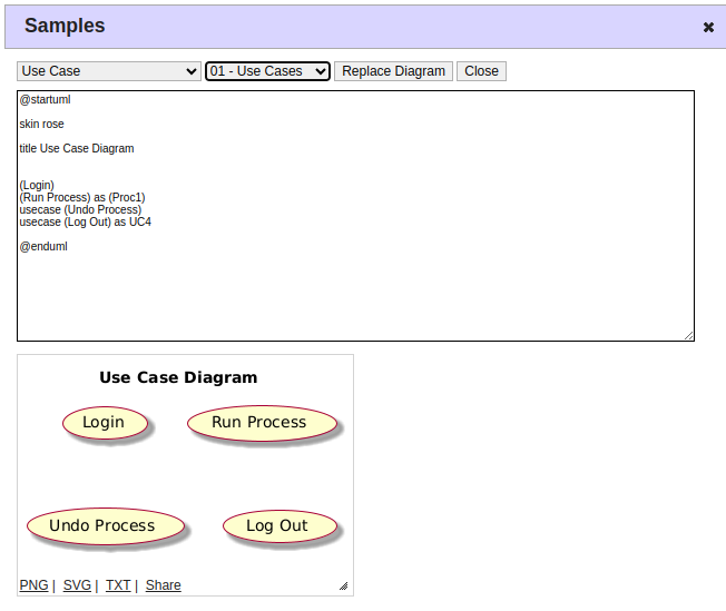
01 – Use Cases
This diagram shows how Use Cases are noted in PlantUML, most simply with parenthesis around the Use Case name.
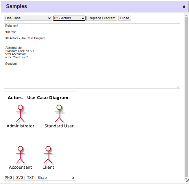
02 – Actors
This sample shows how to represent Actors in PlantUML. The Actor name is simply prefaced with “actor.” Note that Actors can be aliased with the “as” keyword, for convenience in diagrams in which an Actor performs numerous actions.
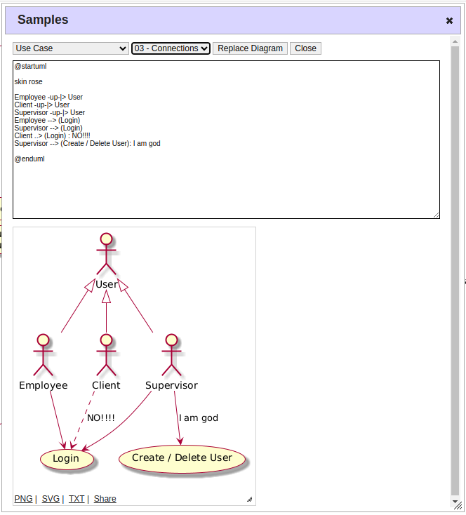
03 – Connections
This sample shows the PlantUML for a variety of associations (connectors) you can use in your Use Case Diagram – solid or dashed – as well as how to point the arrow in the desired direction. Often dashed lines are used to note extends/includes types of associations, where solid lines note simple association (although that is not reflected in the sample below). Open arrows (like those pointing to User) indicate generalization.
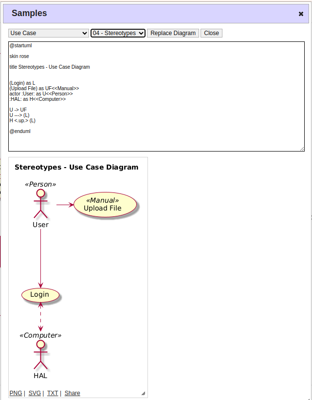
04 – Stereotypes
Stereotypes in a use case diagram indicate when a use case extends, modifies or is a variant of another use case.
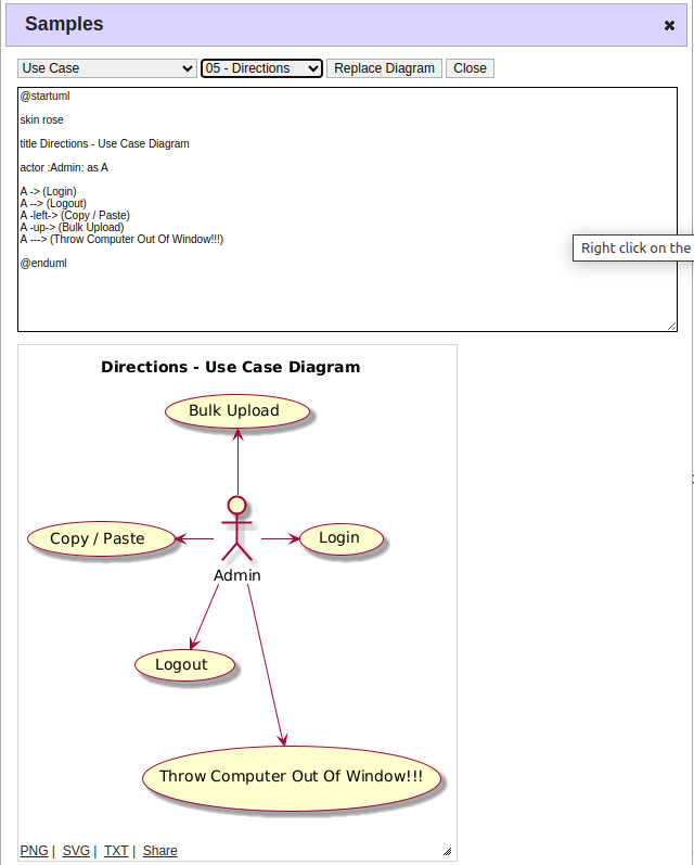
05 – Directions
Most of the time, PlantUML will decide for you where the elements of your diagram will end up. But this sample shows how you can dictate where you want to place one item relative to another. (Note the “left” and “up” keywords.)
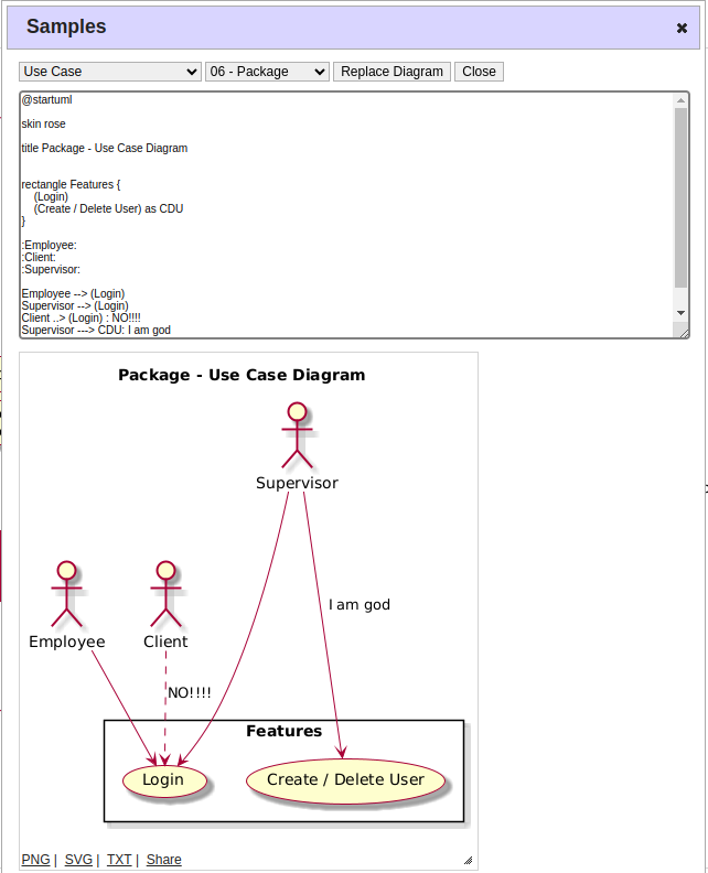
06 – Package
This sample shows how you can wrap multiple elements of your use case diagram into a distinct named Package to define a system boundary.
Putting it all together
Ok, now that we’ve taken a peek at some sample PlantUML for creating different elements of a use case diagram, let’s put it all together in a real-world example.
Let’s say we are building an e-commerce website. Visitors to the site should be able to browse products and sign up for an account. Only registered users can place and cancel orders. We will need a payment gateway to process payments. We’ll also need an administrator role to manage things behind the scenes. Here’s what a use case diagram of this system might look like:
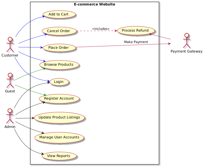
And here’s the PlantUML for generating the above diagram:
@startuml
left to right direction
skin rose

actor Customer
actor "Payment Gateway" as Gateway
actor Admin
actor Guest

rectangle "E-commerce Website" {
  Customer --> (Login) #blue
  Customer --> (Browse Products) #blue
  Customer --> (Add to Cart) #blue
  Customer --> (Place Order) #blue
  Customer --> (Cancel Order)#blue

  (Place Order) --> Gateway: "Make Payment"
  (Cancel Order) ..> (Process Refund) : "<< includes >>"
  Gateway -up-> (Process Refund)

  Guest --> (Browse Products) #green
  Guest --> (Register Account)  #green

  Admin --> (Register Account) #black
  Admin --> (Login) #black
  Admin --> (Update Product Listings) #black
  Admin --> (Manage User Accounts) #black
  Admin --> (View Reports) #black
  }
@enduml
You can read more about the multitude of PlantUML syntax options available for use case diagrams here.
General best practices
For best results with use case diagrams, follow these tips:
- Focus on the external: Remember, use case diagrams are about the external perspective. They don’t show what happens inside the system; instead, they focus on what users want from the system and interactions with other systems.
- Keep it simple: Use case diagrams are meant to be easy to understand. Avoid over-complicating the diagram with too much detail. Stick to high-level actions and interactions.
- Be descriptive: Ensure your use case names are descriptive and clear. Get specific. So instead of something vague like “Manage Data,” try “Create User Account” or “Generate Sales Report” instead.
Wrapping up
Use case diagrams are a powerful tool for software developers, project managers, and business analysts alike. They offer a simple, visual understanding of how users will interact with a system. Creating a use case diagram in the early stages of development can clarify the system’s scope, user interactions, and key functional requirements. And get everyone all on the same page.
Hopefully these examples will give you a head start on building your next use case diagram! And for more diagram types, check out our collection of UML Diagrams.