
Ever tried to explain how your system works and ended up in a 45-minute rant with hand-waving that resembles interpretive dance? Enter sequence diagrams: the ultimate way to sketch out what’s happening, when, and between whom—minus the awkward jazz hands. Whether you’re designing software, documenting processes, or just trying to prove to your team that yes, the backend does talk to the frontend, sequence diagrams have got your back.
In this post, we’ll explore what sequence diagrams are, why they’re incredibly useful, and how to make them in PlantText—because life’s too short for bad design.
What is a sequence diagram?
A sequence diagram is a type of UML (Unified Modeling Language) diagram that shows the interactions between things (objects, actors, or system components) in a time-ordered manner. They’re like a storyboard of your system, but instead of explosions and car chases, you get beautifully ordered steps of function calls and API requests. Sequence diagrams aren’t for showing parallel processes; the focus is on the, ahem, sequence of steps. They’re great for zeroing in on a particular part of a system or process to explore the order of what takes place in more detail.
Sequence diagrams are especially useful for modeling scenarios like:
- User interactions with a system
- What goes on in multi-threaded or asynchronous systems
- API request and response flows…like authentication
- Communication between services or components
- Business process workflows with multiple actors or systems
At its simplest, a sequence diagram consists of:
- Participants: This could be an actor, an entity, a database, or a boundary, among others. The different types of participants each have their own symbol to represent them (see below). And each participant appears with a vertical bar to represent the passage of time.
- Messages: These are horizontal arrows between participants that show the interactions between participants, such as data exchanges or method calls. Typically they’re labeled. Messages are ordered from top to bottom to show what happens, from first to last.
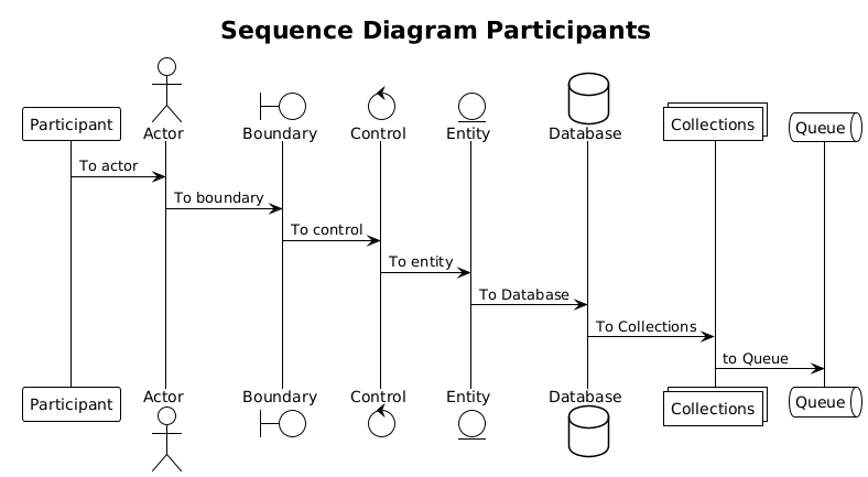
@startuml
!theme plain

title "Sequence Diagram Participants"

participant Participant
actor Actor
boundary Boundary
control Control
entity Entity
database Database
collections Collections
queue Queue

Participant -> Actor : To actor
Actor -> Boundary : To boundary
Boundary -> Control : To control
Control -> Entity : To entity
Entity -> Database: To Database
Database -> Collections : To Collections
Collections -> Queue : to Queue
@enduml
Why use sequence diagrams?
So why do we use sequence diagrams? Because chaos is bad, my friend. Sequence diagrams are probably one of the easier diagrams for someone new to UML because they don’t involve the complexities of decisions, loops and parallel processes. Generally I find that I don’t begin constructing sequence diagrams until we’re a little further down the road on a project. First I need to understand the overall big picture of what we’re trying to accomplish, and activity diagrams are great for that. When I’m ready to zoom into the details of a particularly complex or tricky area in the overall process or system, I create a sequence diagram to lay out all the details.
In other words, they are great for the design phase of the software development life-cycle. Here are some great reasons to use sequence diagrams:
- Design clarity: They lay out system interactions visually, making it easier to explain complex processes so even your least technical stakeholder gets it.
- Documentation gold: Perfect for reference when you inevitably forget why you built something the way you did.
- Finding errors: By mapping out interactions, teams can spot potential design flaws before they become full-blown disasters.
- Better collaboration: When multiple teams work on different parts of a system, sequence diagrams prevent misunderstandings (and passive-aggressive Slack messages).
How to create sequence diagrams in PlantText
Sequence diagrams are easy enough to create in PlantText. Especially with the Samples window to get you started, and now the new AI window which can create a sequence diagram for you. But here’s how to do it yourself.
- List out your participants in the editor window. Be sure to declare them with the appropriate participant type.
- Specify the messages between participants. These follow a format of
sender -> receiver : message.
In this example we have a web application, and we want to examine what all is going on with respect to authentication / authorization when a protected resource is requested. Seeing the process broken down explicitly to each step really clears up any ambiguity.
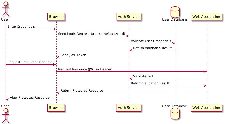
In PlantUML we declare the participants (User, Browser, Auth Service, User Database and Web Application in this case). And we spell out each step happening in sequence in the format of sender -> receiver : message.
Boom. Now everyone knows what’s going on, and you don’t have to explain it five more times in meetings.
@startuml
skin rose

actor User
participant "Browser" as Browser
participant "Auth Service" as AuthService
database "User Database" as UserDB
participant "Web Application" as Website

User -> Browser : Enter Credentials
Browser -> AuthService : Send Login Request (username/password)
AuthService -> UserDB : Validate User Credentials
UserDB -> AuthService : Return Validation Result
AuthService -> Browser : Send JWT Token

User -> Browser : Request Protected Resource
Browser -> Website : Request Resource (JWT in Header)
Website -> AuthService : Validate JWT
AuthService -> Website : Return Validation Result
Website -> Browser : Return Protected Resource
Browser -> User : View Protected Resource

@enduml
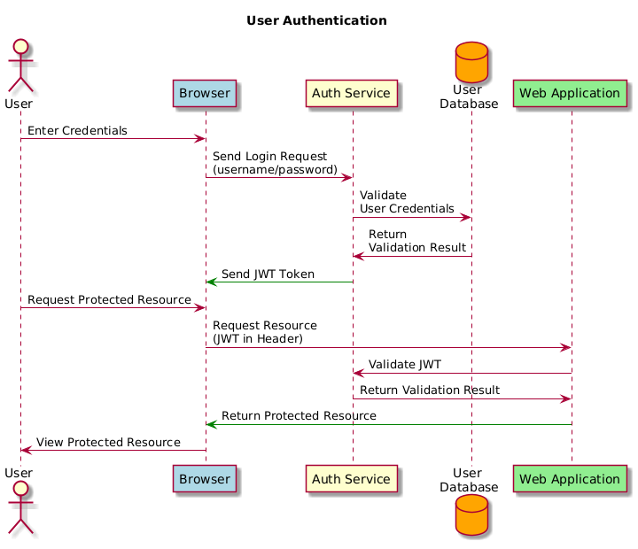
Getting Fancy
Creating a basic sequence diagram is easy enough, right? But maybe we want to add a few extra touches.
- First off let’s add a title.
- Some of those messages are kind of long. They’re stretching our diagram out width-wise, so let’s make them wrap.
- And maybe we want to color code some things.
@startuml
skin rose

Title "User Authentication"

actor User
participant "Browser" as Browser #lightblue
participant "Auth Service" as AuthService
database "User \nDatabase" as UserDB #orange
participant "Web Application" as Website #lightgreen

User -> Browser : Enter Credentials
Browser -> AuthService : Send Login Request \n(username/password)
AuthService -> UserDB : Validate \nUser Credentials
UserDB -> AuthService : Return \nValidation Result
AuthService -[#green]> Browser : Send JWT Token

User -> Browser : Request Protected Resource
Browser -> Website : Request Resource \n(JWT in Header)
Website -> AuthService : Validate JWT
AuthService -> Website : Return Validation Result
Website [#green]-> Browser : Return Protected Resource
Browser -> User : View Protected Resource

@enduml
And actually sequence diagrams can get a lot fancier than this. You can…
- Auto-number messages when things get busy.
- Add notes for extra details, and alter their shape or styling.
- Group messages for more complex processes.
- Change the alignment of items.
- Use a variety of arrow types.
Learn more about the myriad options for sequence diagrams here.
Pro tips for kick-ass sequence diagrams
You want your sequence diagrams to be the best they can be. Here are a few tips to keep you from going astray:
- Keep it simple: Avoid overcrowding diagrams with too many details. Focus on the essential.
- Use meaningful labels: Messages should have clear, concise names that describe the action.
- Organize participants: Place participants in an order that makes sense for the order of the process.
- Limit the number of participants: If a diagram gets too complex, break it down into smaller, modular diagrams.
- Test your diagram: Walk through the sequence step by step to ensure it actually makes sense.
Why use UML anyway?
Some folks may wonder, is it really necessary to diagram application details like this? Why not just get everyone together, discuss it and move on?
Look, I get it—drawing diagrams isn’t as thrilling as pushing code to prod and praying. But sequence diagrams (and UML in general) save you from future headaches.
Because when you skip design and opt for a casual conversation, who’s to say everyone in the room will walk away with the same understanding? If each person is responsible for their own notes according to their own system, who’s to say everyone’s version of the facts will be in agreement? You won’t uncover discrepancies until much later, when changes are costlier to make. And when Frank comes back from vacation a week later to begin coding his part of the system, will he even remember what was said?
UML diagrams provide a common language for a team to use. They reduce ambiguity because they remove the flourishes of grammar from the underlying meaning of the message being conveyed. They serve as a contract or a blueprint for what should be built. They lay out the rules unambiguously for all to follow.
Trust me. You need UML.
To wrap up: Sequence diagrams for the win
Sequence diagrams are an amazing tool for laying out system interactions step-by-step. Whether you’re designing APIs, modeling microservices, or improving workflow processes, they provide clarity and structure to your projects. With PlantText, creating and refining sequence diagrams is quick and simple (unlike debugging production issues at 3 AM).
So what are you waiting for? Head over to PlantText and give it a shot. Your future self will thank you.
Oh, and if you want to explore other diagram types, check out our series on UML Diagrams.