
What Are Class Diagrams?
This post is all about creating Class Diagrams using PlantUML. We’ll start with the basics of PlantUML syntax, and then chat a bit about object oriented programming. I’m mostly writing this post as a refresher for myself, as well as a reference for future me. True confession – I keep forgetting the syntax because I go just long enough between building class diagrams. But the new “Snippet” functionality helps with that.
Building class diagrams is not a quick and easy thing for people (especially non-programmers) to get started doing. It requires a lot of prerequisite knowledge in object oriented programming and universal modelling language (UML), as well as familiarity with diagramming tools like PlantText. Only then can you get started building your diagram. So why not just get cracking writing code in your favorite language? Why even bother building UML diagrams in the first place?
Why Use Them?
I hate to say it, but in my career I have noticed that most people and companies are terrible at designing software. They just jump right in, start coding, and think that taking an agile project management framework approach is going to make it all work. There are a million books out there (like Peopleware, Joel On Software, Death March, and all the Steve McConnell books) that talk about the terrible track records of software projects. Half of all software projects fail completely, and many others just limp along.
The point is that spending a significant amount of the project’s time doing formalized requirements and design work upfront and iteratively (along with following an iterative process like agile scrum) is the best way – in my experience – to build software that succeeds. It’s also the best way to figure out early on if the software shouldn’t even be written at all! Please – don’t just get started implementing in your favorite language. Do some design work!
It is All About Communication
So, assuming that actually designing software is a good thing, why build class diagrams? Well, there are a lot of UML diagram types, but class diagrams in particular are used to quickly prototype the important entities within the primary applications of a system. Class diagrams help you visualize the number, complexity, and relationships between these entities. And, they allow you to do this in a way that is programming language agnostic. I may be a C# developer, while you are a Python programmer. It doesn’t matter. We see the same nouns, verbs, and relationships in the blocks of code. Also, class diagrams are understandable enough that non-programmers and managers can be more involved as well.
I don’t usually bother with complete system /API class diagrams. Nobody needs them when they can just look at the completed code. I just create small class diagrams to help communicate effectively in design documents, emails, and presentations. A picture is worth a thousand words. Maybe when the project is over you never even look at them again, but they helped you communicate an idea when it mattered. I personally build mostly sequence, activity, use case and class diagrams to help with visual communication.
Creating Class Diagrams with PlantUML
But I digress. Let’s jump into learning the basics of building class diagrams. PlantUML is funny in that it doesn’t really follow the exact rules of the official OMG UML specification (found here). But, it can be made to look pretty close to it .
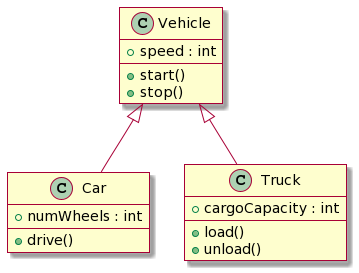
So here is a small API for Vehicles. This is a really simple diagram to build but the details tell you a lot. You can see the properties and methods for all the interfaces and classes. The plus (+) sign means they are all public. Also, you can see the relationships between the entities via the relationship arrows. Notice the top entity is an interface, so all the classes like Car, Truck, and Motorcycle implement this interface. Also, I try not to repeat the members for each implementing class. The dashed line in the arrows let you know that Vehicle is an interface.
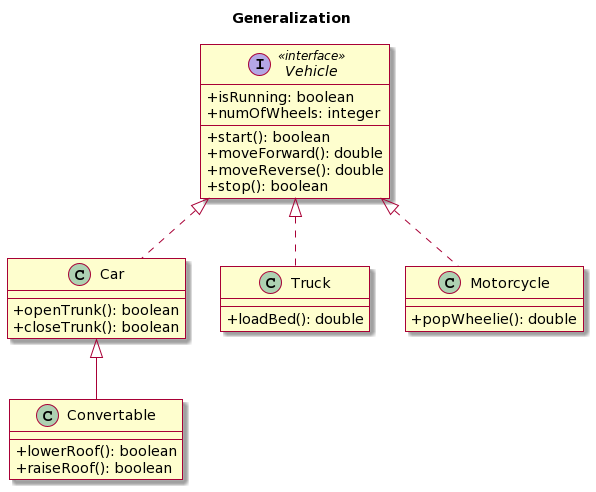
The Convertible class extends the Car class, so notice the solid line on that relationship. Anyway, this is how you communicate Generalization in UML and PlantUML.
Creating Properties & Methods
As you can see below, you can set the fields and methods accessibility / visibility using the syntax below. In our simple diagram everything is public, which is usually where you start.
@startuml

skin rose

class Example {
 -privateField
 #protectedField
 ~packagePrivateField
 +publicField

 -privateMethod()
 #protectedMethod()
 ~packagePrivateMethod()
 +publicMethod()
}

@enduml
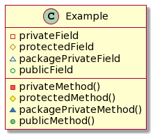
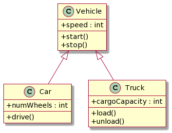
Below are a couple more class diagrams built in PlantUML. They have exactly the same meaning, but look slightly different. The default syntax in PlantUML uses colored shapes to illustrate the property and method accesibility (public, private, protected, etc.). Adding the “skinparam classAttributeIconSize 0” line switches it back to a more standard UML look with (+, -, #) approach.
@startuml

skin rose

skinparam classAttributeIconSize 0

class Vehicle {
  + speed : int
  + start()
  + stop()
}

class Car extends Vehicle {
  + numWheels : int
  + drive()
}

class Truck extends Vehicle {
  + cargoCapacity : int
  + load()
  + unload()
}

@enduml
@startuml

skin rose

'' skinparam classAttributeIconSize 0

class Vehicle {
  + speed : int
  + start()
  + stop()
}

class Car extends Vehicle {
  + numWheels : int
  + drive()
}

class Truck extends Vehicle {
  + cargoCapacity : int
  + load()
  + unload()
}

@enduml

These are all the accessibility options. Notice the difference between UML and PlantUML.
| UML | Fields | Methods | Visibility |
- |  |  | private |
# |  |  | protected |
~ |  |  | package private |
+ |  |  | public |
And here are the basic relationship options. You can find the full list and more here.
| Type | Symbol | Drawing |
| Extension | <|-- |  |
| Composition | *-- |  |
| Aggregation | o-- |  |
Relationship Types
So, let’s dive into the relationship types and think about what they mean in actual C# code snippets. I use C# here but you can think about it in any language you like.
Generalization (Inheritance)
- Represents the “is-a” relationship
- Subclasses are specializations of the SuperClass
- Dashed line is used when the SuperClass is an abstract class (or Interface)
- A solid line is used with when not abstract
- In C# you just use the implements syntax as in orange below
PlantUML:
@startuml

skin rose

class Vehicle {
  + speed : int
  + start()
  + stop()
}

class Car extends Vehicle {
  + numWheels : int
  + drive()
}

class Truck extends Vehicle {
  + cargoCapacity : int
  + load()
  + unload()
}

@enduml
C#:
public class Vehicle
{
    public int speed;
    public void start(){}
    public void stop(){}
}

public class Car : Vehicle
{
    public int numWheels;
    public void drive(){}
}

public class Truck : Vehicle
{
    public int cargoCapacity;
    public void load(){}
    public void unload(){}
}
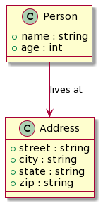
Simple Association – Link Between classes
- Any structural link between two classes
- Usually directional
- Is a solid line in most cases
- In C# all it takes is to have a public member of the other class type to create this relationship
PlantUML:
@startuml

skin rose

class Person {
  + name : string
  + age : int
}

class Address {
  + street : string
  + city : string
  + state : string
  + zip : string
}

Person --> Address : lives at

@enduml
C#:
public class Person
{
    public string name;
    public int age;

    public Address address;
}

public class Address
{
    public string street;
    public string city;
    public string state;
    public string zip;
}
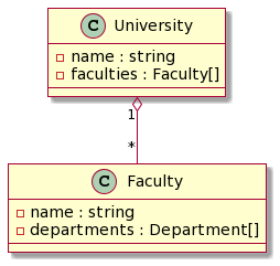
Aggregation
- Represents the “part of” relationship
- One class is a part of another
- Many instances (*) of Faculty can be associated with the (1) of University
- Objects of University and Faculty have separate lifetimes.
- A solid line with an empty diamond at the association end connected to the class
- In C# you see the private list of Faculties and a AddFaculty method to pass them in
PlantUML:
@startuml

skin rose

class University {
  - name : string
  - faculties : Faculty[]
}

class Faculty {
  - name : string
  - departments : Department[]
}

University "1" o-- "Many" Faculty

@enduml
C#:
public class University
{
    private string name;
    private List<Faculty> faculties;

    public University(string name)
    {
        this.name = name;
        this.faculties = new List<Faculty>();
    }

    public void AddFaculty(Faculty faculty)
    {
        this.faculties.Add(faculty);
    }
}

public class Faculty
{
    private string name;
    private List<Department> departments;

    public Faculty(string name)
    {
        this.name = name;
        this.departments = new List<Department>();
    }

    public void AddDepartment(Department department)
    {
        this.departments.Add(department);
    }
}
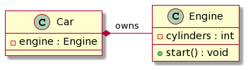
Composition
- Represents the “part of” relationship, but an instance of one class being destroyed, destroys instances of the other class
- The “part” class cannot stand on its own
- If there is a multiplicity again you can use many instances (*) and (1) one the connector
- A solid line with a filled diamond at the association connected to the class
- In C# notice that the deconstructor set the Engine to Null. If the instance of an object is instantiated within the scope of a method, that is composition too (very very common)
PlantUML:
@startuml

skin rose

class Car {
  - engine : Engine
}

class Engine {
  - cylinders : int
  + start() : void
}

Car *- Engine : owns

@enduml
C#:
public class Car
{
    private Engine engine;
    public Car(Engine engine)
    {
        this.engine = engine;
    }

    ~Car()
    {
        Console.WriteLine("Car object destroyed");
        this.engine = null;
    }
}

public class Engine
{
    private int cylinders;
    public Engine(int cylinders)
    {
        this.cylinders = cylinders;
    }

    public void Start()
    {
        Console.WriteLine("Engine started");
    }

    ~Engine()
    {
        Console.WriteLine("Engine object destroyed");
    }
}
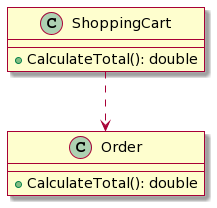
Dependency
- Changes to the definition of one may cause changes to the other (but not the other way around)
- Weaker type of relationship between two classes where one class depends on the other class for some functionality but has no ownership or control over it
- The lifetime of the dependent class is not controlled by the lifetime of the independent class
- Represented in class diagrams by a dashed arrow pointing from the dependent class to the independent class
- In C# notice the orange line that makes the ShoppingCart dependent on the CalculateTotal() method of Order
PlantUML:
@startuml

skin rose

class ShoppingCart {
    +CalculateTotal(): double
}

class Order {
    +CalculateTotal(): double
}

ShoppingCart ..> Order

@enduml
C#:
public class Order
{
    public double CalculateTotal()
    {
        // Calculation logic here
        return 0.0;
    }
}

public class ShoppingCart
{
    public double CalculateTotal()
    {
        Order order = new Order();
        double total = order.CalculateTotal();
        // Other logic here
        return total;
    }
}
So now what?
First off, remember to use PlantText Snippets to quickly create a Class or a type of Relationship without using your mouse. This is a very efficient way to work with Class Diagrams. Just make sure to login and then go to the Settings window to select the “Class” snippet category.
And now that we’ve got the basics of building class diagrams under our belts, let’s take it to the next level. In my next series of posts, I’ll be taking a look at some of the most common “Gang of Four” (GoF) Design Patterns. If you’re not familiar with this seminal book on object oriented programming patterns, you can find it here. We’ll be starting off looking at the Singleton design pattern. Stay tuned for my next post!